Łożyska - 2014-08-20
Diagnose Misalignment
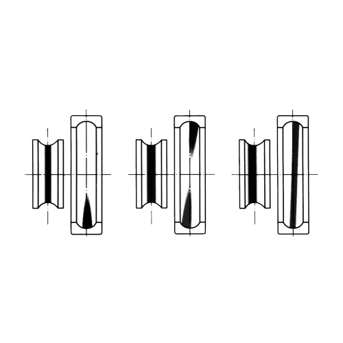
Misalignment in a failed bearing can typically be diagnosed by examining the rolling element path inside the bearing. As bearings rotate, the rolling elements generate a wear path on the inner and outer raceways. A well-aligned bearing will exhibit a running path down the center of the inner and outer rings, while a misaligned bearing will exhibit uneven running paths (see Figure 1).
Avoid Misalignment
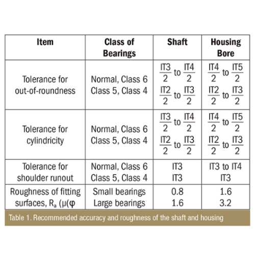
Misalignment can be avoided by being attentive during the bearing installation process. The first step is the proper design and machining of the mating housing and shaft components. Housings should be rigid to provide firm bearing support. In cases in which two bearings are mounted in one housing, the fitting surfaces of the housing bore should be designed so both bearing seats may be finished together with one operation, such as in-line boring. The recommended accuracy and surface finish of shafts and housings are listed in Table 1 for normal operating conditions (IT values are International Tolerances Grades as per the International Organization for Standardization 286). The shoulders of the shaft or housing that contact the face of a bearing must be orthogonal to the shaft center line.
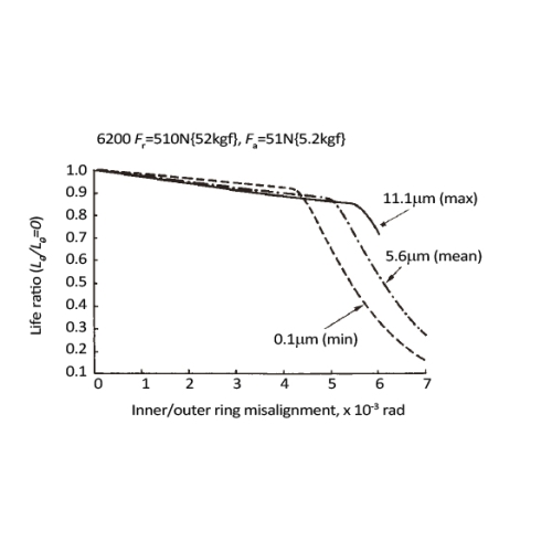
The fillets of the shaft and housing should not contact the bearing chamfer, while the supporting shoulder diameter still must be large enough to fully support the face of the bearing. During installation, all mating surfaces should be cleaned, and all shaft and shoulder abutting surface edges should be free of burrs. Bearing mounting methods will vary depending on the bearing type and the type of fit. Because bearings are usually used with rotating shafts, the inner rings require a tight fit. Bearings with cylindrical bores are usually mounted by pressing through the inner ring on the shafts (press fit) or heating them to expand their diameter (shrink fit). Bearings with tapered bores can be mounted directly on tapered shafts or on cylindrical shafts by using tapered sleeves. Bearings are usually mounted in housings with a loose fit. However, if the outer ring has an interference fit, a press may be used. End users should always apply a light film of oil on the fitting surfaces first to prevent scoring. When pressing a bearing into a housing, apply press to the outer ring of the bearing. When pressing onto a shaft, press on the inner ring. Mitigate the Effects on Bearing Life Several bearing solutions are available to help mitigate the effects of misalignment. For example, nylon cages are more flexible than steel cages and can accommodate misalignment better than steel cages. Increasing the internal clearance of the bearing will increase its misalignment capacity. Self-aligning ball bearings can also be used. These bearings have a spherical raceway with a center of curvature that coincides with that of a bearing. This allows the axis of the inner ring, balls and cage to deflect to some extent around the bearing center. However, this design can create a smaller contact angle between the ball and the raceway, which results in a lower load capacity compared to a similar sized, deep-groove ball bearing. The permissible static misalignment in this bearing type is approximately 0.07 to 0.12 radian (4 to 7 degrees) under normal loads. Depending on the surrounding structure, this angle may not always be possible. Because standard L10 calculations assume that the bearing is well-aligned, additional calculations must be made to determine the effect of misalignment on the bearing’s fatigue life. The maximum allowable misalignment of a bearing varies depending on the size and type of bearing, internal clearance during operation, and the load. Assume the fatigue life without misalignment as Lθ 0, and the fatigue life with misalignment as Lθ. The effect of the misalignment on the fatigue life can be found by calculating Lθ/Lθ=0. Figures 2 and 3 show the effect of misalignment on the life ratio for a deep groove ball and roller bearing, respectively. In these figures, the horizontal axis shows the misalignment of inner/outer rings (rad), while the vertical axis shows the fatigue life ratio Lθ/Lθ=0. As an example of ordinary running conditions, the radial load Fr (N) {kgf} for both figures was assumed to be approximately 10 percent of the dynamic load rating Cr (N) {kgf}, and the shaft fit was machined to the recommended value.
The decrease of the internal clearance because of the expansion of the inner ring was also considered. Figure 2 was generated using the normal radial clearance for the deep groove ball bearing. The three separate plots represent maximum, minimum and mean effective clearance. The reduction of the fatigue life is limited to 5 to 10 percent up to 0.004 radian of misalignment, therefore, not significantly reducing the bearing life. However, when the misalignment exceeds this limit, life is reduced considerably. In this scenario, an increase of 11μm in internal clearance results in ~0.0015 radian increase in misalignment capacity.
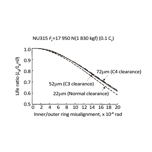
Figure 3 plots three separate clearance classes for a cylindrical roller bearing: normal, C3 and C4 clearance. In comparison to Figure 2, the life ratio is reduced by more than 10 percent with only 0.001 radian of misalignment. Little variation between the different clearance classes exists, despite a total difference of 50μm.
Clearly, the roller bearing is more sensitive to the effects of misalignment than the ball bearing, and this should be considered when selecting a bearing type in a new pump design. These figures were generated for typical operating conditions but are not applicable to all pump applications. Reducing or eliminating misalignment is critical to long bearing and pump life. Catalog-recommended assembly tolerances and installation processes must be followed to prevent bearing misalignment. If misalignment cannot be completely avoided, additional calculations are required to determine the effect it will have on the bearing life. Contact a bearing manufacturer for assistance with these calculations and additional application analyses.
Proszę wybrać…
